


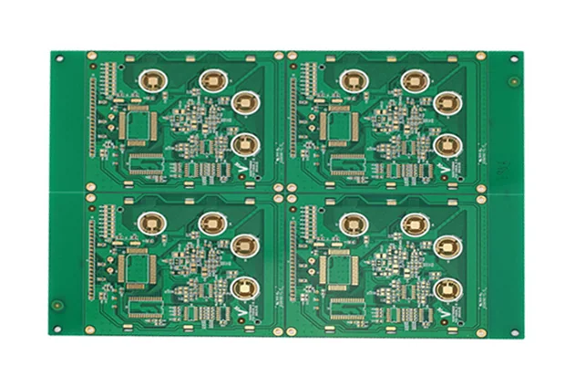
The conclusion first: when a panel will not close, the arithmetic is rarely the problem. Five processes have made conflicting demands on the same tooling rail, and nobody has been given the authority to decide who yields.
On many projects panelization is treated as the last layout step. The board is finished, the outline is frozen, and someone asks the fabricator how many up a panel can hold. That phrasing already shrinks the problem. Panel count is an output, not an input.
What the panel drawing actually decides is: where resin flows during lamination, what drilling and imaging use as a datum, how plating current distributes near the panel edge, where force enters and travels during routing and depaneling, and whether the machine has anything to grip during SMT.
All five share one physical region: the tooling rail and the structures connecting board to board. Once you see that they share the same real estate, "how many up" stops being an independent question. It is whatever number remains after those five constraints hold simultaneously.
1. What each process wants from the rail
| Process | What it wants | Why it is hard |
|---|---|---|
| Lamination | Enough edge region for resin to flow and escape | Resin flow is physical; boundary conditions govern inner dielectric uniformity |
| Drilling and imaging | Stable, sensibly distributed datums | Datums define the coordinate system for every later layer; on an unreliable datum, compensation is meaningless |
| Plating | Edge copper distribution not too far from centre | Current density follows copper distribution, and edge effect writes straight into deposit thickness |
| Routing and depaneling | Short, straight, predictable fracture or cut paths | The force path decides where stress travels, and stress does not route around components |
| SMT | A grippable rail, recognisable fiducials, a supportable underside | A board with no clamping region cannot enter the line; this is binary, not a matter of degree |
What matters in this table is not any single row. It is that they all point at the same region. There is only one rail. Datums fit in a limited number of places. The connecting structure, once chosen, acts on routing, depaneling and SMT at the same time. So this is not five requirements that can each be optimised. It is a shared-resource allocation problem.
There is a sixth participant that rarely gets named: material utilisation. It is not a process, but it is present at every review, and its demand runs opposite to most of the five above. It wants narrow rails, dense nesting, little empty space. This is why panelization discussions turn into tug-of-war: five technical requirements on one side, a cost pressure running through all of them on the other, and the two sides not speaking the same language.
2. Which pairs are inherently opposed
Several conflicts here are structural. They are not caused by poor communication and they do not disappear when different people negotiate.
Rail width versus material utilisation. The most direct pair. The clamping region SMT needs, the resin-flow region lamination needs, and the datum region drilling needs all land on the rail, and each wants it wider. Utilisation wants it narrower. There is no technical resolution to this pair, only a decision — it is a pure cost-versus-risk trade.
Connection strength versus depaneling stress. The connection between boards must be strong enough that the panel does not come apart during handling, conveyor transfer and the oven pass. The same structure must be weak enough at depaneling that separating it does not drive force into the board. This is one structure required to exhibit opposite properties at two different moments. Strengthen it and depaneling stress rises; weaken it and intermediate risk rises. The whole difficulty of break-tab design lives here, not in how the tabs are drawn.
Datum placement versus nesting density. Datums need to be spread out, need to be asymmetric (or a reversed panel presents an identical pattern and the machine raises no error), and need to sit where no fixture or carrier will cover them. Each of those requirements consumes panel area that nesting density wants for boards.
Edge copper distribution versus nesting freedom. Plating edge effect relates to copper distribution near the panel edge, and that distribution is a by-product of the nesting arrangement — how boards are oriented, whether the rail carries copper, whether auxiliary copper areas exist. Bringing edge conditions closer to centre conditions means the arrangement cannot be purely utilisation-optimal.
What these four share: none can be eliminated by working more carefully. They are oppositions between constraints, resolvable only by deciding who yields first.
3. The order in which margin is released
Since someone must yield, the order is the only real engineering content in this decision. The sequence below runs from cheapest to most expensive, judged by whether yielding at that step leaves an unrecoverable consequence.
First, yield material utilisation. It is the only participant whose concession carries no quality consequence. The cost of one more strip of scrap is definite, calculable and one-time. An insufficient rail that prevents SMT clamping, or an unreliable datum that produces layer-to-layer misregistration, are problems that keep recurring in downstream operations. Putting the cost item ahead of the quality items is the least contentious rule in the sequence.
Second, yield the depaneling method. If the tension between connection strength and depaneling stress cannot be resolved, change the method rather than continuing to tune parameters inside one method. Routed break-tabs, V-scoring, and a mix of the two have entirely different force characteristics (next section). Switching route is a process choice with a defined cost; tuning repeatedly inside an unsuitable route defers the cost to volume production.
Third, yield nesting density. By this point you are trading area for conditions: fewer up, so datums have somewhere to sit and edge copper distribution has room to be adjusted. The cost is higher than the first item (output per panel falls) but it is still calculable.
Fourth, and only then, touch datums and rail width. These come last because yielding on them is unrecoverable. With unreliable datums, every subsequent compensation is built on a wrong coordinate system. With an insufficient rail, SMT may simply not be possible — and that is not "slightly worse", it is whether the operation happens at all.
Last, revisit the board outline itself. If all four concessions are made and it still does not close, what needs to change is not the panel but an upstream premise: the single-board outline, or the assembly flow. This is the most expensive move available, and it is still cheaper than forcing an unworkable panel into production.
> To be explicit: this order is a general principle, not a decision to copy. Which step yields first in a given project depends on that board's actual structure, assembly flow and volume. The value of the order is that it provides a discussion framework — so that every concession is explicit and recorded, rather than quietly absorbed by whichever operation sits downstream.
4. How the depaneling method constrains the panel in reverse
The previous section said "yield the depaneling method". Here is what that means in practice. Depaneling is not a downstream choice made after the panel is fixed. It decides how the panel can be arranged at all.
Routed break-tabs. Boards are routed apart with a few connecting tabs left. The advantage is outline freedom — curves, concave features and irregular contours are all producible. The cost is that tab count, position and cross-section simultaneously decide "will it survive handling" and "how much force does depaneling take", and those two goals oppose each other. Tab position carries one constraint that is often missed: it has to stay clear of stress-sensitive components and structures, because depaneling force enters the board through the tabs and the nearer a component sits, the more it absorbs. Which means tab position cannot be decided during panelization alone; it needs the component layout.
V-scoring. Grooves on both faces leave a web that is broken at depaneling. The advantages are a short path, high throughput and good material utilisation. The cost is that it requires straight, continuous lines running across the whole panel. As soon as one board outline is non-rectangular, or adjacent board edges are not collinear, V-scoring will not lay out. In addition, board regions adjacent to a score see bending during the break, so that zone is unsuitable for stress-sensitive structures — again a design input, not a depaneling detail.
Mixing the two. V-score on the main direction, routing for irregular features, is the most common real arrangement. It captures both advantages and introduces one new problem: the junction where a V-score meets a routed slot is the weakest point on the panel. Two different separation mechanisms converge at one location, and connection strength there is governed neither by the score nor by the tab. A mixed scheme has to address those junctions explicitly, rather than treating them as the natural consequence of each method's own boundary.
The choice among the three is not about which is better. It depends on whether the outline lets V-scoring work, and where the component layout permits tabs. Which is why the depaneling discussion has to happen before the nesting arrangement, not after.
5. Which fields belong to design, and which to the fabricator
The failure point in panelization is usually not technical judgement but a blurred responsibility boundary, where each side assumes the other will decide something. Split by "who holds the information" and the boundary is actually clear.
Must come from design (the fabricator cannot obtain these):
- Component layout and stress-sensitive zones. Which components, joints or structures cannot take depaneling stress. A fabricator cannot tell which component is sensitive.
- Board-edge keep-outs. Which regions near the edge must carry no copper, no components, or must not be touched by a clamp.
- Available datum locations. Which regions will not be covered by a carrier, clamp bar or frame during assembly. A covered datum does not exist.
- The critical constraints of the assembly flow. Double-sided placement or not, wave soldering or not, press-fit operations, large or tall components. These determine what the panel must satisfy at SMT.
- Which edges are functional. Which edges are mating faces that go into an enclosure and need tighter dimensional or cosmetic treatment, and which are ordinary contour. Not distinguishing means the whole board gets judged at the highest requirement, which wastes effort on both sides.
- When depaneling happens. Whether the panel ships intact for the customer to separate, or the fabricator separates and ships singles. This changes the premise of the entire connection design.
Should be left to the fabricator (fixing these in design locks out workable solutions):
- Panel count and nesting arrangement. These depend on the fabricator's material formats, machine travel and fixturing — all fabricator-side information.
- Specific rail width. Same reason: set by equipment and process window.
- Tab count and cross-section, V-score parameters. Process parameters, determined by actual equipment and material.
- Datum form. Within the locations design has made available, determined by the fabricator's vision recognition requirements.
There is a simple test for this split: if the correct answer depends on what equipment and material the factory has, design should not fix it; if it depends on what this board plugs into and where it must not take load, the factory has no way to know and design must supply it.
The matching cadence: before releasing drawings, design puts "how is this board going to be gripped and separated" to the fabricator as an explicit question; the fabricator returns a panel scheme and keep-out zones; both confirm, then the design freezes. Producible board types and process boundaries are on manufacturing capabilities; acceptance classes and the inspection framework are described under quality; orderable multilayer build ranges are on multilayer PCB; assembly-side conditions are on PCBA services.
6. Boundaries against adjacent questions
This article covers one thing: who gets the margin on the rail. Several adjacent questions already have their own articles, so these are pointers only:
- How outline and V-cut tolerances should be called out → outline and V-cut tolerance
- Where outline machining deviation originates → outline machining tolerance
- How layer-to-layer registration is controlled during lamination → multilayer lamination registration control
- Support and distortion on the second side of a double-sided board → double-sided second-side reflow placement
- How a stack-up is read and planned → multilayer PCB stackup guide
FAQ
Q1: Who actually decides the panelization?
Both, split by information. Nesting arrangement, panel count, rail width and tab parameters belong to the fabricator, because they depend on material formats and equipment. Stress-sensitive zones, board-edge keep-outs, available datum locations, assembly-flow constraints and which edges are functional must come from design, because none of it is visible in the Gerber. Only the two sets combined produce an executable panel scheme; either side deciding alone locks out the other's feasible solutions.
Q2: Why can the outline not be frozen first and panelization asked about afterwards?
Because the depaneling method constrains the outline in reverse. V-scoring requires straight, continuous lines running across the whole panel; as soon as a board is non-rectangular or adjacent edges are not collinear, that route does not exist. Switching to routed tabs then requires tabs placed clear of stress-sensitive components, which returns you to the layout. So the sequence should be: settle the depaneling method while the outline is still changeable. Asking after the outline freezes typically ends with discovering a method is unavailable, and by then changing the outline drags layout and enclosure mating faces with it.
Q3: V-score or routed tabs — which is better?
The question has no general answer, because the two have entirely different limiting conditions and do not sit on one axis of merit. V-scoring gives a short path, high throughput and good utilisation, but demands straight continuous lines, cannot produce irregular outlines, and bends the zone adjacent to the score during the break. Routed tabs give outline freedom including concave features, but tab strength is inherently torn between surviving handling and keeping depaneling force low, and tab position is constrained by component layout. The deciding inputs are whether the outline lets V-scoring work and where the layout permits tabs.
Q4: What needs special attention when mixing the two?
The junctions. Where a V-score meets a routed slot is the weakest point on the panel: two separation mechanisms converge there, and connection strength is governed neither by the score nor by the tab. A mixed scheme must mark and address those junctions explicitly rather than treating them as the natural by-product of each method's boundary. Mixing is common and sensible; the problem appears only when the junctions are treated as belonging to neither party and nobody owns them.
Q5: Why can the fabricator not just place the datums itself?
The fabricator can determine datum form and exact coordinates within an available region, but not which regions are available. If a datum is covered by an assembly carrier, clamp bar or frame, the equipment cannot see it — and that information exists only in the assembly flow, which the fabricator does not have when the Gerber arrives. So the correct split is design supplying available locations and keep-outs, and the fabricator fixing form within that envelope according to its vision requirements. A covered datum and no datum are the same thing.
Q6: If all five concessions are made and it still will not close, what does that mean?
It means the thing to change is not the panel but an upstream premise: the single-board outline, the assembly flow, or the volume and delivery form (intact panel versus singles). That step is the most expensive, which is why it comes last — but it is far cheaper than pushing an unworkable panel into production. An unworkable panel does not become workable further downstream. It gets cashed in one item at a time, through SMT clamping, depaneling stress or layer misregistration, and by then each repair costs more than changing the outline would have.