


Products
Resin Plugged Via PCB
- Plugging processes
- Conventional screen printing / vacuum resin plugging
- Vacuum equipment capability
- Absolute pressure below 50 Pa
- Demonstrated fine line/space
- 3.5/3.5 mil (4-layer halogen-free FR-4 sample)

Technical Specifications
| Specification | Value |
|---|---|
| Plugging processes | Conventional screen printing / vacuum resin plugging |
| Vacuum equipment capability | Absolute pressure below 50 Pa |
| Demonstrated fine line/space | 3.5/3.5 mil (4-layer halogen-free FR-4 sample) |
| Demonstrated copper weight | 2 oz (2-layer FR-4 sample) |
| Demonstrated surface finishes | ENIG / lead-free HASL |
| Applicable structures | Buried, small, thick-board and via-in-pad vias; stack-up confirmation applies |
Process Flow
The exact route changes with via type and stack-up; these are the principal control points reviewed by engineering.
- 1Confirm plugging locations, via types and stack-up intent
- 2Drill and metallize the via walls
- 3Fill with resin and cure to the qualified material conditions
- 4Planarize the via surface and inspect its condition
- 5Continue lamination, drilling or imaging as required by the build
- 6Perform visual, electrical and microsection checks as agreed
Product Features
- Conventional screen-printing and vacuum resin-plugging processes
- Applicable to buried vias, small vias, thick boards and via-in-pad structures
- Vacuum plugging equipment with absolute pressure below 50 Pa
- Filling, curing and ceramic planarization controlled for via integrity
- Halogen-free FR-4, ENIG, lead-free HASL and impedance designs supported
- Inspection plans can combine visual, electrical and microsection checks
Design Considerations
- Identify every resin-plugged via in the fabrication drawing and state whether capped or via-in-pad treatment is required.
- Use consistent via definitions and units across Gerber, drill, stack-up and impedance documentation.
- Do not treat resin plugging and solder-mask plugging as interchangeable; their materials, functions and acceptance criteria differ.
- Review pad geometry, via diameter, copper construction, aspect ratio and lamination sequence as one system.
- State any void, dimple, protrusion or microsection acceptance criteria in the RFQ documentation.
Applications
HDI and high-density interconnect designs
Via-in-pad land structures
Buried vias in multilayer boards
Fine-pitch packages requiring a planar surface
Sequential lamination constructions
Reliability-focused interconnect designs
Resin-Plugged-Via Gallery
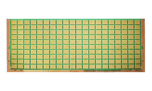
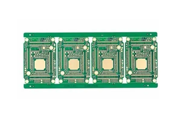
These images show PCB panels and via layouts used for resin-plugging process review. The actual plugged structure, fill condition and acceptance result are defined by project fabrication data and inspection records.
FAQ
How does resin plugging differ from solder-mask plugging?
- Resin plugging: fill, cure, planarise. Mask plugging: solder-mask closure. Specify separately.
Which designs may require resin-plugged vias?
- Buried vias · via-in-pad · sequential lamination; subject to project review.
What files are needed for a resin-plugged-via quotation?
- Gerber / ODB++ · drills · stack-up · material/copper · plugging and plating callouts · acceptance criteria.
How are resin-plugged-via limits confirmed?
- Confirmed by project review of the complete stack-up and fabrication data.
Related Products



Need a quote for Resin Plugged Via PCB?
Submit fabrication data, stack-up and plugging requirements for a project-specific manufacturability review and quotation.
Get Quote Now